|
|
|
|
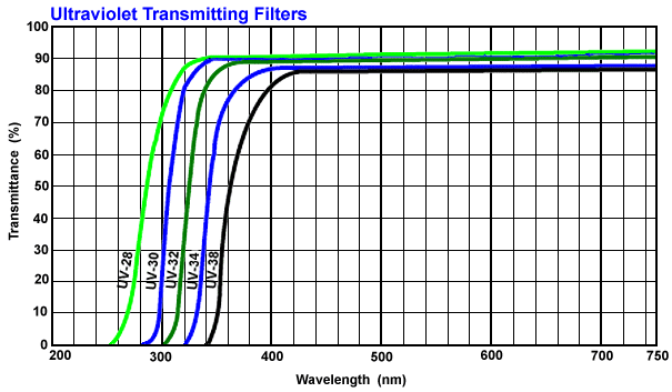
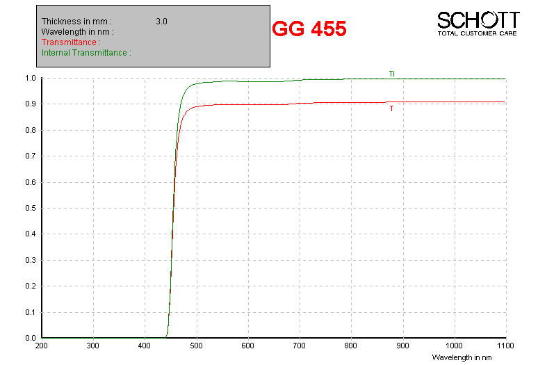
Note: All gratings are used in first order only. Second order contamination is removed through the use of order-blocking filters, described below.
Mechanical limitations require that the camera angle be quantized to every 0.75 degrees, with a maximum articulation of 100 degrees. Thus, a finite (but still large) number of camera positions are available. The camera angle determines the central wavelength on the detector, with longer wavelengths associated with larger camera articulation angles.
The angle of the grating also affects spectral resolution. The higher the value of the grating tilt, the higher the spectral resolving power for a given slit width.
Use the VPH grating spectroscopy simulator to determine the optimal grating angle and slit width for your observation.
| Grating | Wavelength Coverage |
Usable Angles (degrees) |
Bandpass per tilt (nm) |
Resolving Power (1.25 arcsec slit) |
|---|---|---|---|---|
| SR300 | 370-900 | |||
| G0900 | 320-900 nm | |||
| G1300 | 390-900 nm | |||
| G1800 | 450-900 nm | |||
| G2300 | 380-700 nm | |||
| G3000 | 320-540 nm |
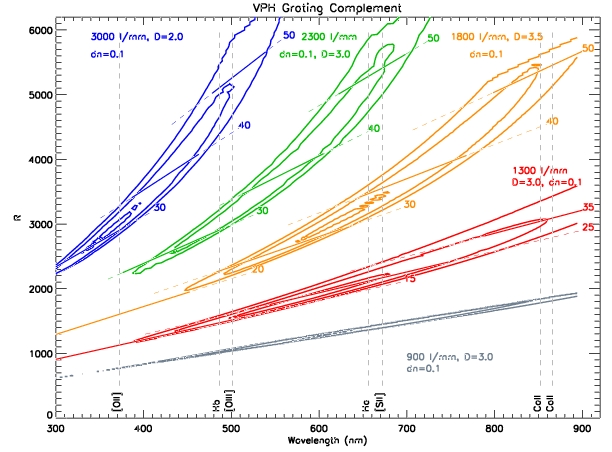
Below is a contour plot of the VPH grating efficiencies, as calculated using Rigorous Couple Wave (RCW) analysis, in resolving power versus wavelength. The contours correspond to 90%, 70%, and 50%. Wavelength coverage for a few angles are shown for each grating.
The choice of slit widths is driven by considerations of resolution and throughput. A variety of slits will be available to cover the range of atmospheric seeing conditions expected at the site. For the SALT site, the median seeing is 0.9 arcseconds at the zenith. Seeing varies approximately as

For the SALT telescope, where the zenith distance is 37 +/- 6 degrees, the factor by which the seeing is degraded from the zenith seeing is 1.14 +/- 0.05. Furthermore, the telescope (plus SAC) imaging error budget is 0.6 arcseconds. Therefore, the median spot size at the PFIS focal plane is 1.2 arcsec.
The PFIS slitmask magazine has room for ten tilted longslits. These allow for the SALT Imaging Camera (SALTICAM) to be used as a slitjaw viewing camera. The complement of longslits will include:
| Slit Width (arcsec) |
Slit Throughput for zenith seeing of |
||
|---|---|---|---|
| 0.6 arcsec | 0.9 arcsec | 1.8 arcsec | |
Peakup holes are cut into the mask and correspond to the focal plane positions of reference stars. Peaking up the position of the slits on the sky requires several images taken at slightly different telescope pointings. The CCD control computer will sum and report the counts within pre-programmed sub-arrays on the chips, and the PFIS computer will command the telescope to the position that produced the highest throughput.
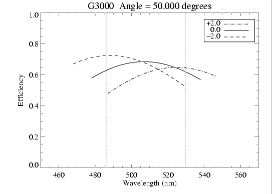
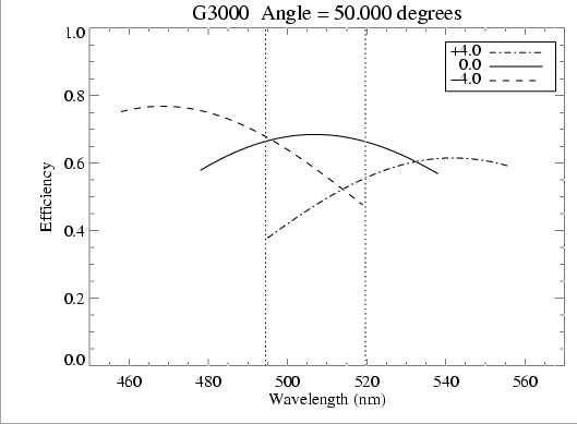
One specific characteristic of VPH gratings to keep in mind is that the wavelength dependence of the efficiency depends on the input angle to the grating. In multi-object spectroscopy, the light entering through off-axis (in the dispersion direction) slits will hit the grating at different angles. Thus, the efficiency for the off-axis objects will be different than for the on-axis objects. This will in general not be symmetric either, i.e. objects that are at +2 arcminutes off-axis will have a different wavelength dependence of the efficiency from those at -2 arcminutes off-axis.
Additionally, the wavelength coverage on the detector for off-axis objects will be different than that for on-axis. So, the simultaneous wavelength coverage for a given grating setup with a multi-object slit mask will depend on how far off-axis the objects are.
The following two plots demonstrate these effects. They show, for the G3000 grating at 50 degrees grating angle, what the wavelength coverage and efficiency for the on-axis and two off-axis positions is. Note that for the full field (4 arcminutes off-axis) the simultaneous wavelength coverage is reduced and the efficiency can be as much as 50% lower for certain wavelengths.
When contemplating multi-object observations, be sure to use the VPH grating spectroscopy simulator to look at the efficiency curves for the off-axis positions.